2 Pipe Hvac System Diagram
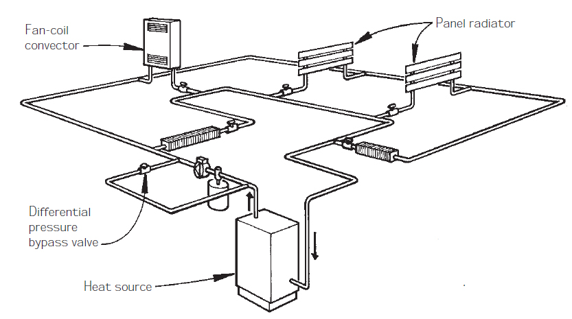
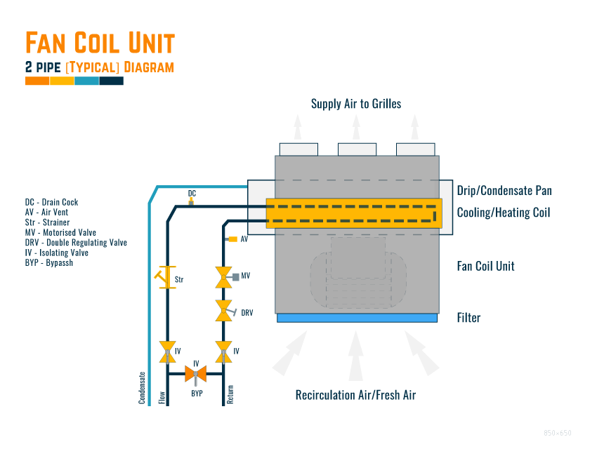
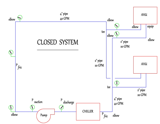
2 pipe hvac system diagram. Each radiator has a smaller hot water supply pipe branched off the main feed pipe to supply the radiator the water passes through the radiator coming out the other side a little cooler and then mixed. The entire building is in either heating mode or cooling mode. An HVAC systems piping consists of four insulated pipes.
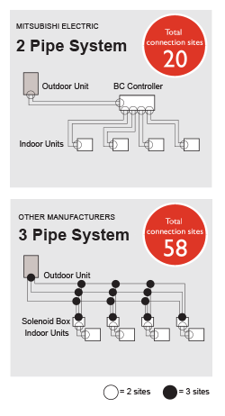
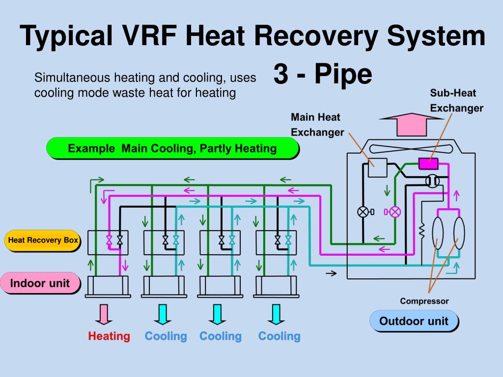
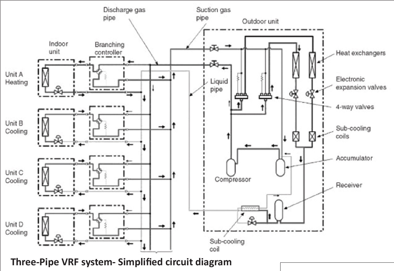
There are different parts for a HVAC system based on its application but one can consider what occurs in a evaporative cooling system as a widely used case throughout the world and get a sense of what is generally happening in the system. Each manufacturer has its own proprietary design 2-pipe or 3-pipe system but most uses a three-pipe system liquid line a hot gas line and a suction line and special valving arrangements. 65222 Heating Ventilating and Air Conditioning Two-Pipe Changeover System.
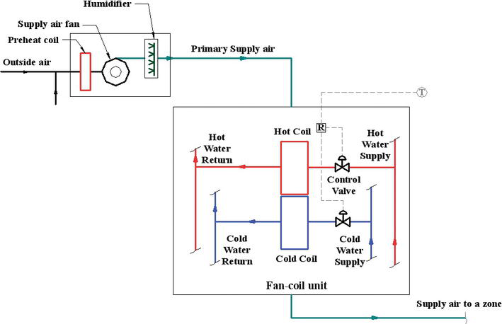
Since chilled water systems have high efficiency they are used in many large buildings. Use it for drawing HVAC system diagrams heating ventilation air conditioning refrigeration automated building control and environmental control design floor plans and equipment layouts. In addition a four-pipe system requires more space to accommodate two hydronic piping circuits that run through the building.
This system configuration uses twice as much piping as a two-pipe HVAC system and thus it is more expensive and takes longer to install. One of the systems with the most comfort complaints is a Two Pipe System. A supply and a return.
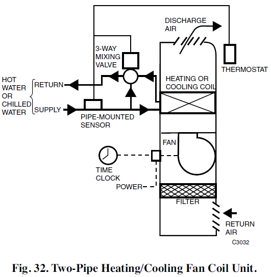
Maximum Equivalent line length in Feet 25 50 75 100 150 18000 15 ½ ½ ½ ⅝ ⅝ 24000 2 ½ ⅝ ⅝ ⅝ ⅝ 30000 25 ½ ⅝ ⅝ ⅝ ¾ 36000 3 ⅝ ⅝ ⅝ ¾ ¾. The two pipe system is the most commonly used configuration in the installation of hydronic central heating systems. The changeover from heating to cooling or vice versa is made manually and there is always the possibility that unusual weather patterns might cause some occupant discomfort.
Meaning if alterations to the system design or units are made after parts are ordered costs could potentially increase. Another set of pipes is dedicated to hot water generally kept between 150 and 200 degrees Fahrenheit. The vector stencil library HVAC equipment contains 84 HVAC equipment symbols as pumps fans condensers pipe coils silencers etc.
Two supply lines and two return lines. Two Pipe System - Hydronic Central Heating.
Wire the tank or systempipe sensor connected to the DHW sensor terminals on the follower boiler addressed as 1.
The vector stencil library HVAC equipment contains 84 HVAC equipment symbols as pumps fans condensers pipe coils silencers etc. Changeover sensor or switch- TO1 TO2 are not used- AO2 is not used This is the configuration required. An indoor unit requiring cooling will open its liquid line and suction line valves. Meaning if alterations to the system design or units are made after parts are ordered costs could potentially increase. The required system pipe diameter for example may change if the indoor unit capacity indoor unit type or pipe length fluctuates. A supply and a return. Overall the majority of the buildings on campus. Use it for drawing HVAC system diagrams heating ventilation air conditioning refrigeration automated building control and environmental control design floor plans and equipment layouts. This is a diagram of the obsolete one-pipe pumped system.
Each manufacturer has its own proprietary design 2-pipe or 3-pipe system but most uses a three-pipe system liquid line a hot gas line and a suction line and special valving arrangements. Reset controls are provided that allow heating and cooling supply temperatures at the changeover point to be no more than 30F apart. Each radiator has a smaller hot water supply pipe branched off the main feed pipe to supply the radiator the water passes through the radiator coming out the other side a little cooler and then mixed. Overall the majority of the buildings on campus. In addition a four-pipe system requires more space to accommodate two hydronic piping circuits that run through the building. 4 0560-TD 0117 Table I Discharge Line System Capacity BTUHr. Changeover sensor or switch- TO1 TO2 are not used- AO2 is not used This is the configuration required.
















Post a Comment for "2 Pipe Hvac System Diagram"